Difference between revisions of "Example io demo"
(→Usage Example. Input to Output Demo) |
(→Usage Example. Input to Output Demo) |
||
| Line 95: | Line 95: | ||
Note that we connect PortC pin0 to PortB pin0; PortC pin1 to PortB pin1; etc. | Note that we connect PortC pin0 to PortB pin0; PortC pin1 to PortB pin1; etc. | ||
| + | |||
<pic closeup pins labelled> | <pic closeup pins labelled> | ||
Here's our homemade cable plugged into the GPIO header. | Here's our homemade cable plugged into the GPIO header. | ||
| − | |||
| − | |||
| − | |||
<pic> | <pic> | ||
Revision as of 14:53, 12 December 2013
This is a guide to the io demo C example project included in the EMAC OE SDK.
IO is an acronym; it stands for Input Output. It refers to data going in and data coming out. In and out of what you ask? Why your machine of course. In this case your machine is the SOM-150ES carrier board.
Input is data going into your machine. Your machine is receiving data, via a port or header, from an external piece of hardware. Mouses, joysticks, keyboards, electronic rain-guages, digital telescopes, burglar alarms and the internet: these all produce streams of data that your machine can store, process, fold, weave and otherwise react to. What your machine does with the data, specifically, depends what software you've got running.
Output is data coming out of your machine. Your machine is sending data, via a port or header, to an external piece of hardware. It's telling that piece of hardware to do something: store some bytes of data, blink an LED, wiggle a robotic tentacle. What data gets sent depends on what software you've got running.
Combined, that's IO. It's how your machine converses with the outside world and without which it is just a sexy paperweight.
The io demo gives us four nice demonstrations of SOM-150ES carrier board IO. We keep it simple. As you might imagine there are some extremely sophisticated IO technologies out there (USB, Ethernet...) but that's a discussion for another time. Here we're just going to work with a general purpose input output (GPIO) header. It's straightforward stuff. Understanding the principals outlined here will equip you to hold meaningful digital conversations with anything from a toaster to a space shuttle.
Contents
Opening, Building and Uploading the Project Files
1. Open the C/C++ editing perspective.
stub
2. Open the io demo project files.
stub
3. Build the io demo project.
stub
4. Upload the io demo binary to the target machine.
stub
Usage and Behaviour
Hardware Requirements
To use the io demo program you will need the following hardware.
- A SOM-150ES carrier board (Available from EMAC).
- A compatible SoM for that carrier board (SOM-9260M, SOM-9G20M and SOM-9X25 are all compatible and available from EMAC).
- A multimeter or oscilloscope. See Usage Example. Input to Output Demo and Usage Example. Count Demo for details.
- A scrap of homestyle ribbon cable just long enough to reach from GPIO Port B to GPIO Port C. See Usage Example. Input to Output Demo for details.
- An analog signal generator. See Usage Example. A/D Demo for details.
Usage for io_demo
Execute io demo from the console. It takes no parameters.
./io_demo
This brings up a menu of demos.
****************************
     Demo Menu

A/D Demo             - a
Count Demo           - c
Input to Output Demo - i
Ring Demo            - r

Exit                 - x

Enter Selection:
Now we can press a,c,i or r to run a demo; or x to exit.
Usage Example. A/D Demo
STUB. NEED AN ANALOG WAVEFORM GENERATOR TO USE THIS did somebody say something about there already being an analog out built right onto the carrier board?
Usage Example. Count Demo
From the demo menu press c.
The system counts from 0 to 255 in binary. It takes about 15 seconds to complete.
The steps of this process are reflected in the GPIO PortC header pins. As each bit in our 8bit register is set to 1, the corresponding pin in the PortC header momentarily registers 5 volts (easily detected with a multimeter or oscilloscope).
More visibly, the process is also reflected in the strip of 8 LEDs on the board (LD1-LD8). A lit LED indicates a 1 in our 8 bit register and an unlit LED indicates a 0. When the counting process is finished all 8 LEDs are lit.
Usage Example. Input to Output Demo
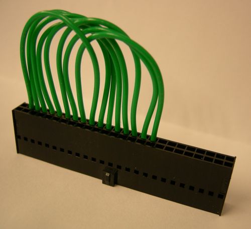
In this usage example the SOM-150ES carrier board talks to itself. We send an 8bit data stream directly from Port B to Port C via a short piece of ribbon cable.
Here's our homemade cable plugged into the GPIO header

Note that we connect PortC pin0 to PortB pin0; PortC pin1 to PortB pin1; etc.
<pic closeup pins labelled>
Here's our homemade cable plugged into the GPIO header.
<pic>
Our data stream for each pin is 1,0,1,0,1,0... That is to say: all pins are set to 1, then they are all set to 0, then to 1 again, etc. We observe our data stream in the strip of 8 LEDs on the carrier board. They blink in unison.
NOTE The blinking may get a little out of synch. Don't be alarmed.
<pic> (animated GIF?)
Usage Example. Ring Demo
Refer to the SOM-150ES carrier board surface mount LEDs LD1-LD8 for output.
The board lights the LEDs in numeric sequence, 1-8, then repeats; looping until a key is pressed.