Difference between revisions of "Example io demo UPDATE 2019"
| Line 25: | Line 25: | ||
OR | OR | ||
* an IPAC <br /> | * an IPAC <br /> | ||
| − | |||
| − | |||
====Carrier Board==== | ====Carrier Board==== | ||
Revision as of 16:30, 2 July 2019
This demo covers basic gpio usage for the IPAC single board computer, and 150 and 200 series carrier boards. This demo first cover gpio manipulation through the Linux terminal and then demonstrates gpio usage in a C program using an io example program.
Setup
Usage and Behavior
Hardware Requirements
To use the io demo program you will need the following hardware.
- An EMAC SOM-150ES carrier board with a compatible SoM
OR
- An EMC 200 carrier board with a compatible SoM
OR
- an IPAC
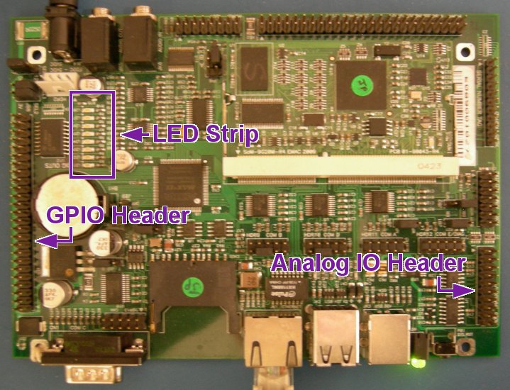
Carrier Board
This is a detail of the HDR1 PLD & BUFFERED GPIO header. Pin 49 is Vcc. The bottom pins: 2, 4, 6...46, 48, 50; are all ground. Port A is pins 1, 3, 5, 7, 9, 11, 13, 15. Port B is pins 17, 19, 21, 23, 25, 27, 29, 31. Port C is pins 33, 35, 37, 39, 41, 43, 45, 47.
The output shows the stray charge on the inputs being read by the analog-to-digital converter on pins 11, 12, 13, 14. Press a a few times to watch the values change.
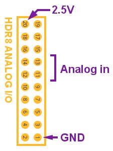
This is the HDR8 ANALOG IO header.
Let's do a couple of experiments on our analog in pins.
Connect pin 20 to pin 11 and hit a. Note that the first value is higher than the others. It should read approximately 3FF. This means that the first analog-in pin has 2.5V on it.
Connect pin 1 to pin 11. Hit a. Note that the first value is lower than the others. It's the vicinity of 0. That means that the first analog-in pin is pulled down to ground.


