Difference between revisions of "Getting Started with the DEV-IOT6U"
m |
|||
| (5 intermediate revisions by the same user not shown) | |||
| Line 9: | Line 9: | ||
<!-- /*********************************************************************************************************/ --> | <!-- /*********************************************************************************************************/ --> | ||
This page outlines a basic guide to getting starting using the DEV-IOT6U. | This page outlines a basic guide to getting starting using the DEV-IOT6U. | ||
| + | * [[DEV-IOT6U | DEV-IOT6U Hardware Main Page]] | ||
<!-- /*********************************************************************************************************/ --> | <!-- /*********************************************************************************************************/ --> | ||
| Line 39: | Line 40: | ||
* Board Micro-USB to USB Desktop | * Board Micro-USB to USB Desktop | ||
* Board Ethernet to Ethernet Network | * Board Ethernet to Ethernet Network | ||
| − | * 5V Wall Power Supply to Board Power (may be left unplugged from wall until Step | + | * 5V Wall Power Supply to Board Power (may be left unplugged from wall until Step 3) |
3. Open [[Getting_Started_With_Minicom|Minicom]] and create a terminal session with the DEV-IOT6U | 3. Open [[Getting_Started_With_Minicom|Minicom]] and create a terminal session with the DEV-IOT6U | ||
| − | * After supplying power, boot messages will be displayed followed by a log in prompt. | + | * After supplying power, boot messages will be displayed followed by a '''log in''' prompt. |
| − | ** somimx6ul login: root | + | ** '''somimx6ul login: root''' |
| − | ** password: emac_inc | + | ** '''password: emac_inc''' |
* Use command "ifconfig" in the terminal session to find the device's IP address that can be used during the development process. | * Use command "ifconfig" in the terminal session to find the device's IP address that can be used during the development process. | ||
| + | '''Note: USB Port B (JK5) is disabled by default. Jumper JB9 must be in position B followed by command "gpioset gpiochip2 2=0" to enable. This disables the USB Port C (JK7) device port. Reverse the process with JB9 in position A followed by command "gpioset gpiochip2 2=1"''' | ||
== Development == | == Development == | ||
| Line 66: | Line 68: | ||
== Demo == | == Demo == | ||
Proceed to this page for an example demo of the MikroBus Rotary B Click on the DEV-IOT6U: </br> | Proceed to this page for an example demo of the MikroBus Rotary B Click on the DEV-IOT6U: </br> | ||
| − | [[Example_MikroBus_Rotary_on_the_DEV-IOT6U]] | + | *[[Example_MikroBus_Rotary_on_the_DEV-IOT6U]] |
== Further Information == | == Further Information == | ||
| Line 73: | Line 75: | ||
{{:Templateimpl:whatnext | initials=BS | title=Getting Started with the EMAC OE SDK | desc=Basic tutorial for using the EMAC OE SDK. | project=OE 5.0 }} | {{:Templateimpl:whatnext | initials=BS | title=Getting Started with the EMAC OE SDK | desc=Basic tutorial for using the EMAC OE SDK. | project=OE 5.0 }} | ||
| + | * [[DEV-IOT6U | DEV-IOT6U Hardware Main Page]] | ||
* [[Getting_Started_with_the_EMAC_OE_SDK | Getting Started with the EMAC OE SDK]] | * [[Getting_Started_with_the_EMAC_OE_SDK | Getting Started with the EMAC OE SDK]] | ||
* [[Getting_Started_With_Qt_Creator|Getting Started With Qt Creator]] | * [[Getting_Started_With_Qt_Creator|Getting Started With Qt Creator]] | ||
* [[Getting_Started_With_Minicom|Getting Started with Minicom]] | * [[Getting_Started_With_Minicom|Getting Started with Minicom]] | ||
Latest revision as of 10:47, 14 October 2020
This page outlines a basic guide to getting starting using the DEV-IOT6U.
Contents
General Information
What Comes with the Development Kit
- SoM-IMX6U-120R2 (528MHz iMX6UL 4GB eMMC, 128MB SoM, connected to Carrier Board)
- SoM-112ES-131R1 (Dlx Carrier with Wifi/BT & Audio)
- 5V 3A Wall Power Supply
- 10 Pin Com to DB9 Cable 12"
- RJ45 to RJ45 Ethernet Cable 7'
- USB2.0A Male to Micro-USB Male 6'
- 2.4 & 5GHz 100mm Wifi Antenna
- MikroBus ROTARY B click
| NOTE |
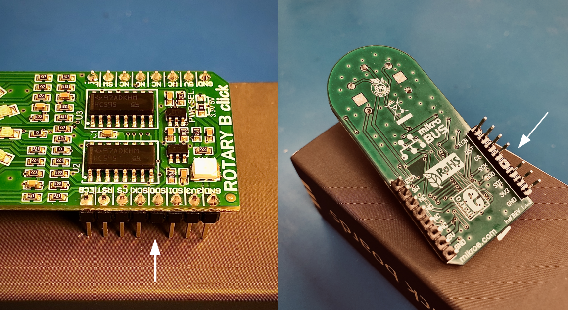
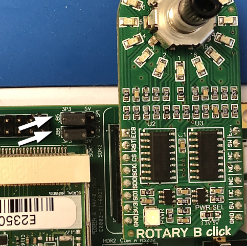
| Do to a design flaw in the MikroBus Rotary B Click, the card does not allow another SPI device to be present on the SPI Bus. The SoM-IMX6U uses the SPI Bus and the presence of MikroBus Rotary B Card prohibits the SOM from booting. To alleviate this issue, the pin labeled “SDO” must be cut and jumpers JB5 and JB6 on the Dev Kit Carrier Board (SoM-112) must be set to 3P3 (see figures below) |
Tools Required
- Desktop PC (Linux or Virtual Linux Machine)
- Instructions for Downloading a Virtual Machine with EMAC OE SDK pre-installed
Setup
1. Install EMAC OE SDK on your computer.
- Installation options are linked HERE.
2. Make the following cable connections using the cables provided:
- Board Micro-USB to USB Desktop
- Board Ethernet to Ethernet Network
- 5V Wall Power Supply to Board Power (may be left unplugged from wall until Step 3)
3. Open Minicom and create a terminal session with the DEV-IOT6U
- After supplying power, boot messages will be displayed followed by a log in prompt.
- somimx6ul login: root
- password: emac_inc
- Use command "ifconfig" in the terminal session to find the device's IP address that can be used during the development process.
Note: USB Port B (JK5) is disabled by default. Jumper JB9 must be in position B followed by command "gpioset gpiochip2 2=0" to enable. This disables the USB Port C (JK7) device port. Reverse the process with JB9 in position A followed by command "gpioset gpiochip2 2=1"
Development
There are two options in development with this device:
1. Using the EMAC OE SDK on terminal. [ Getting Started with the EMAC OE SDK ]
- or
2. Using the EMAC OE SDK on Qt Creator. [ Getting Started With Qt Creator ]
MikroBus Rotary B Click
EMAC has provided a MikroBus Rotary B Card which provide a number of LEDs and a Rotary Switch to allow for easy demonstration and interaction of the Eval Kit. Demo/Example Software is provided that interacts with this Card. This Software can be modified by the user as an exercise in using the development tools.
NOTE: Do to a design flaw in the MikroBus Rotary B Card which does not allow another SPI device to be present on the SPI Bus. The SoM-IMX6U uses the SPI Bus and the presence of MikroBus Rotary B Card prohibits the SOM from booting.
To alleviate this issue, the pin labeled “SDO” must be cut and jumpers JB5 and JB6 on the Dev Kit Carrier Board (SoM-112) must be set to 3P3 (see figures below).


Demo
Proceed to this page for an example demo of the MikroBus Rotary B Click on the DEV-IOT6U: